Gergo Setup
Alright! Now we’re really getting into it!
If you’ve ordered a Gergo: Ready, it’s all ready to go. With the default keymap. For customization skip down to the Configuring Gergo section.
If you have a Gergo: Partial all you need to do is solder in your switches, there’s already a firmware loaded! Just be careful when installing PCB mount switches, be sure to support the board when inserting. Here’s a video on how to solder them.
After that skip on down to the Configuring Gergo section.
Gergo: Kit Assembly
NOTE: There are some differences between Gergo: Wired (Black PCB) and Gergo: Distortion and Protocol (Blue PCB), these are noted below!
NOTE: You can enter programming mode by holding the Rightmost-Lower 1.5u (Right Shift) and plugging Gergo in (or pressing the reset)
IMAGES HERE: https://github.com/germ/GergoDocs
First and formost, I need you to take a nice deep breath. This is going to look like a lot and can be daunting! Trust me with a bit of videos and patience you can do it. Remember, this is a learning experience!
If you’ve never worked with SMD before sit down and give this video a watch.
Reccommended tools: Conical or chisel tip, flux, 0.8mm 37/63 solder, tweezers, desoldering braid, temperture controlled iron.
If you haven’t watched that video, watch it again. Because I’m not telling you exactly what to do here.
Before we do anything at all we need to clean up the board! Grab a dremel or sandpaper and smooth out the rat bites on the edge of the PCB. Wear a mask!
Diodes
We’re going to work easiest to hardest, so let’s start with the diodes. Grab them and carefully empty them into a bowl, tin the pad with a bit of solder and orientate your diode. You’re going to line these guys up under every key switch. You can tell which components are diodes by their irregular pad shape.
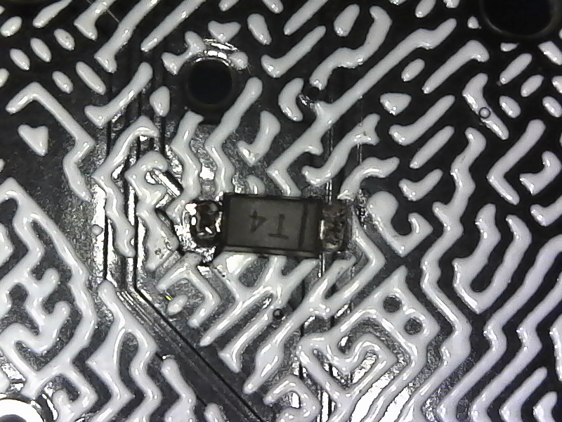
First, you will want to tin the square pads first. Check the image below.
Now, you should put the T near the square pad and let it slide to its rightful place. Do it for all of the diodes so they are lined up.
After that, you should solder the other side of the diode.
Blue PCBs: The diodes are in three lines towards the sides of the board. All your diodes will go here instead of under every switch.
MDF PROTIP: Tin all the square pads before you start. Then heat and slide the diodes into position, finally finish up on the other side!
Caps
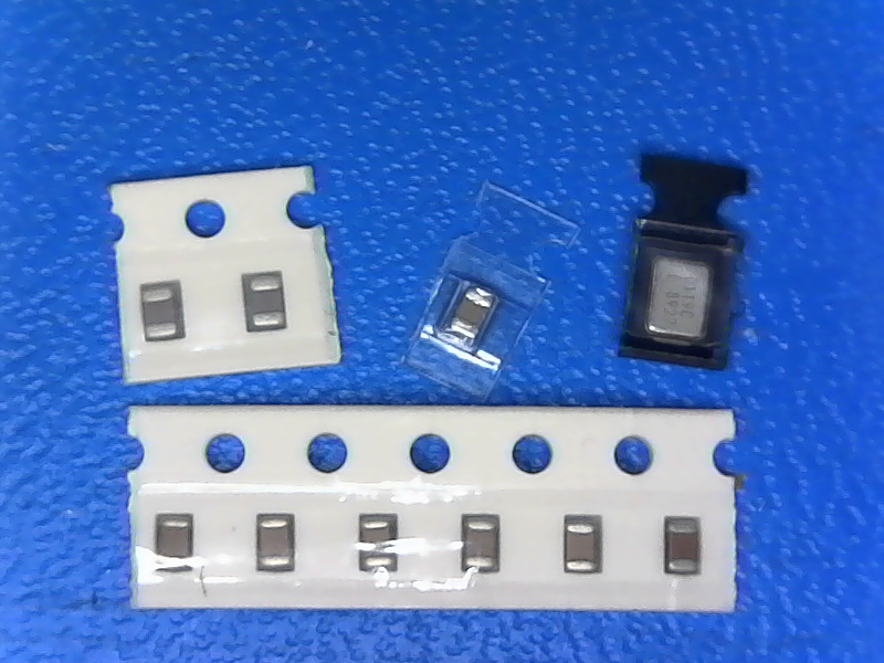
Next up are the capacitors, They’re the little brown guys with no markings. You have three types in this kit.
2x 22pf, 1x 1uf, 5x0.1uF. But, the top right component on the image above is an oscillator.
The function for capacitors is “just to save currents”. So it won’t matter the direction of how you put them.
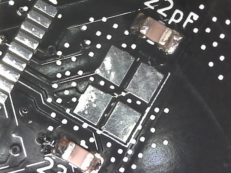
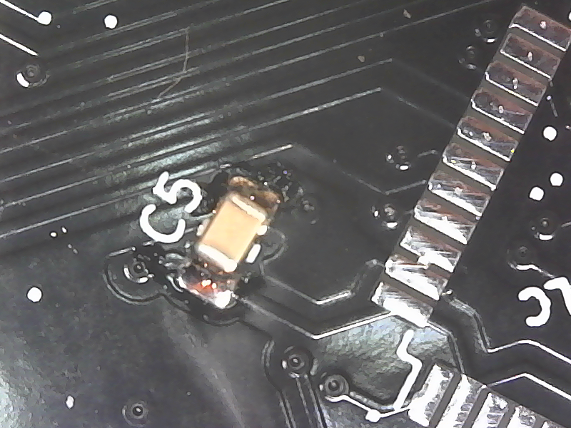
For 22pF capacitors, you should put them around the Oscillator just like the image below.
For 1uF capacitor, you should look around the MCU and put them on the pad which marked by 1uF like the following image.
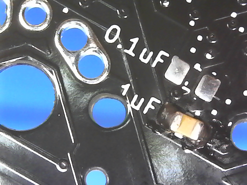
While the rest of the capacitors, 0.1uFs, you should look for pads which marked as such. Check this image below.
Blue PCBs: The 0.1uF Caps are above the MCU in a line and the other is labelled at the top of your board.
Resistors
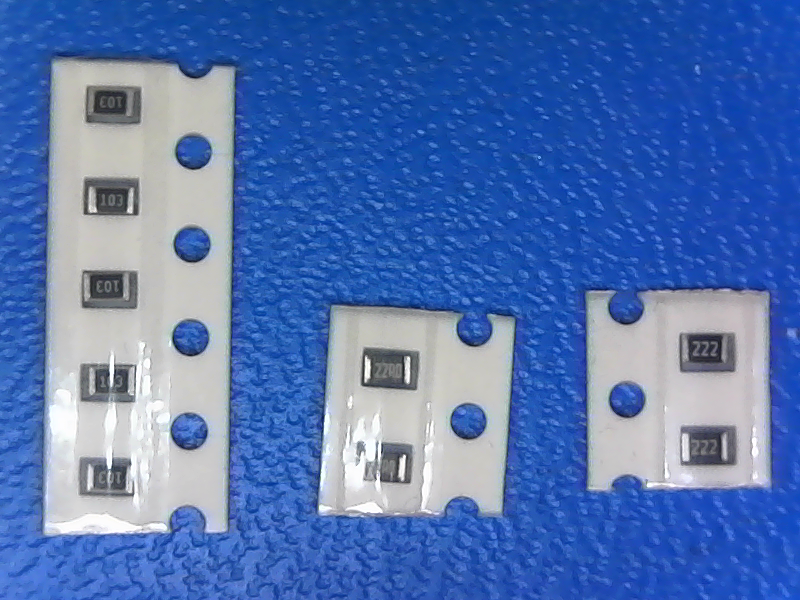
Next up resistors, you’ve got 3 kinds 10K (103), 2.2K (222) 22Ohms (22R0). Take a look on the silk screen for them and whack em in there! They will all be near the MCU or USB port. If you see R1 on your board that’s supposed to be a 2.2K resistor!
Just like capacitors, resistors don’t care about orientation.
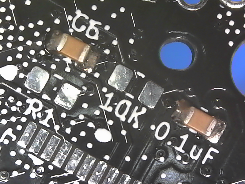
For 10K Ohm resistors (which has 103 label on them), you should put them to pads with 10K marks around them.
While for 220 Ohm resistors (which has 22R0 label on them), you will want to put them around pads with 22 marks around them.
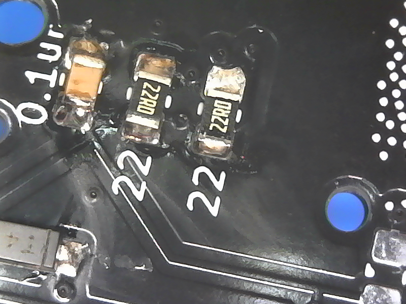
Now, for 2.2k resistors, you should put them around pads with 2.2K marks around them. These resistors connect to the USB, so make sure you put it right.
Osc
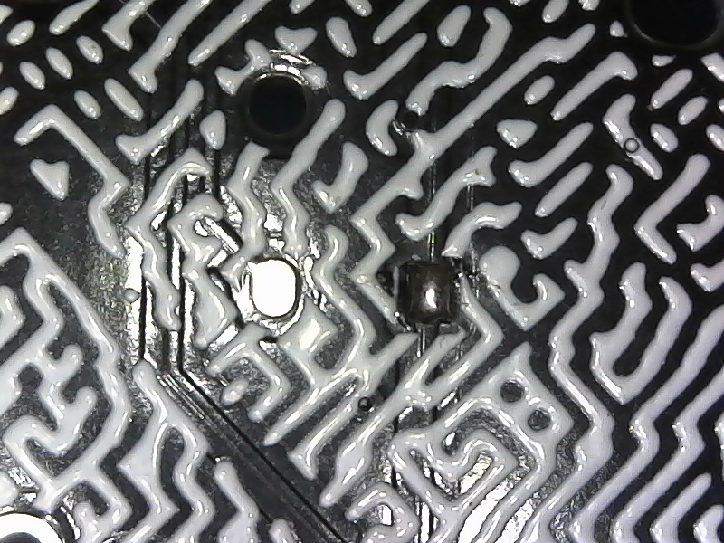
The little recangular guy with four pads is the oscillator, it’s a bit of a pain to solder on to be honest. Orientation doesn’t matter here, but you’ll tin one pad and slide the oscillator into place. After that get the other three legs soldered. Be careful to use as little solder as possible as this guy loves to form solder bridges! Use a continuity tester to be sure. Solder has a way of finding itself on top of the part as well, so you may need to wick that away. Note if you’re probing around in there, these diagonals are connected to each other.

ICs
Lastly the hard stuff! Remember if you mess up, you can order more electronics from the store!
So you should have a few components left, we’re going to start with the MCP (rectangular one). There is a small circle on your PCB and a circle on the IC. Line these up, if it’s missing place the dot towards the top!
Check this image.
Tin a pad on the top corner of it’s pads, heat and align the pins. Be careful! Too much force and you will bend a pin, too long with the iron and you may damage the chip! After it’s aligned do the same to a corner pin on the other side of the board.
Apply flux to the contacts and put some solder on the end of your iron. Do one pin at a time waiting until the solder has flowed before moving onto the next.
Remember to check the warmth of the chip periodically! Check the pins for solder bridges and reflow/wick solder as necessary. You should be able to see gaps between the pins when viewed from the side.
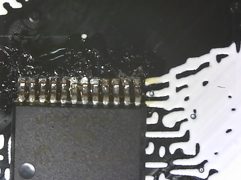
Check this image for the completed result.
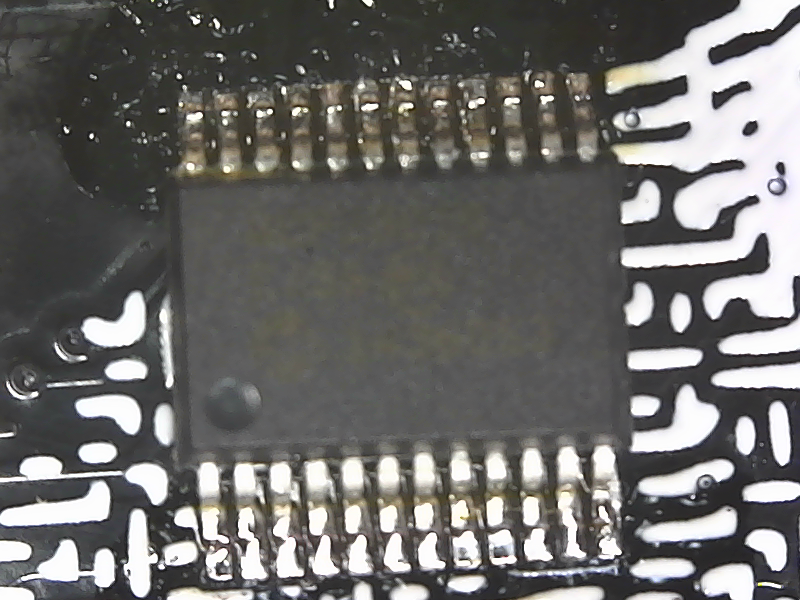
Repeat the same on the MCU. There was a oversight on the silkscreen a bit of background makes it look like there are two places of pin 1. The correct placement of the dot is towards the switches. Here is a image, don’t fuck this up. Also one batch of PCBs has a huge circle instead of a tiny marker, so if you don’t see something like the following image, that giant curved line is supposed to be that tiny circle. Line it up with that image.
Connectors
Assuming you’ve done everything correctly all that is left is the simple stuff! Attach the TRRS jacks using a good amount of solder, same for MiniUSB and the reset switch.
I really suggest you to make MiniUSB’s connection really works first before you continue to the other components.
Use flux for the MiniUSB port and be careful of bridging. If you have problems a little tip is to remove or bend the rear casing using a pair of flush cutters. It just makes getting into position much easier. Be sure to wick out any solder bridges.
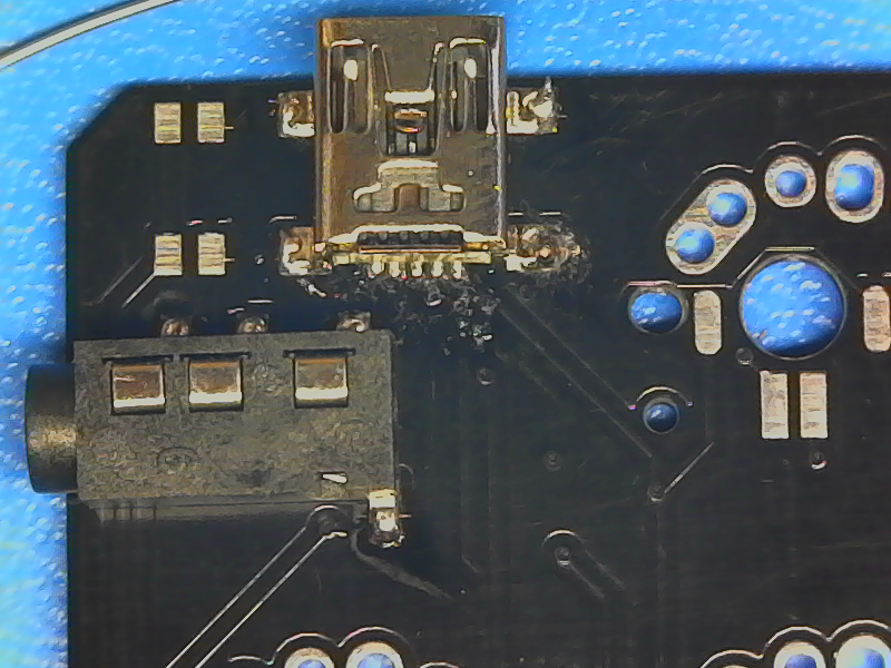
Note For Wired/Distortion: Really glob that solder on there, pull up along the body of the jack to provide a bit more support.
Blue PCBS: The reset may have two plastic pins under it, if it does clip them off before attaching the reset button
Programming/Testing
Alright, we’re in the homestretch. Go off and install these drivers or install dfu-programmer from your repo. We’re going to need them after we run through a checklist.
1) Are there any empty pads on the board?
2) Can you see any solder bridges between pins?
3) Unsoldered all pads on any component?
4) Any diodes in the wrong orientation?
5) Blue PCBs, if you hold the board up to a bright light can you see any bridges on the ICs?
If you answered No to every one of those you’re ready to test! Install those drivers and reboot if you’re a Windows user. If you’ve done everything correctly you should see a Atmel device in Device Manager! Linux users: Run lsusb as root ( watch -n 1 lsusb ). If so, congrats, you’ve done it. Proceed to Install your switches and proceed to configuring Gergo!
If you don’t see your device
If you don’t see a device, that means you did something wrong. Step back, take a breather. Grab a coffee. Leave the board for a while.
Done that? Good. It’s the best advice. Now let’s check some things. We’re going to work backwards from the USB port to the microcontroller.
If you plug it into your USB port and another device on the same bus shuts down
That’s a short. You’ll need to find it and eliminate it, most likely a solder bridge somewhere. If your TRRS cable is connected, disconnect it and see if that solves it.
If you probe around the MCU and don’t see any voltage.
Most likely a problem connecting the USB port, check the solder connections. Might be a good idea to check the orientation of any nearby diodes
Voltage on the MCU, but not showing in Device Manager
Double check your oscillator connections. If you can’t get it to work apply a bunch of solder and gently push it off the board, clean up the board with wick and resolder the oscillator.
Something wonky is happening?
You probably have a unconnected component somewhere. Double check your connections
Still stuck? It might be time to take your board by the local hackerspace. they might be able to help you at their next open house. Otherwise hop into #kb-ergo on the mech keys discord and send me a message.
Building The Trackball
Due to popular request, I made a build video over here.
The first thing I want you to do is to asses if you can build this thing, it’s small, finicky and a pain in the ass. That being said now is a good time to asses if you’d rather pop a MX switch in there. This revision is a touch janky and jittery due to the low amount of resolution on the sensors!
Stil want to do it? Right on. Lets get this out of the way, your chances of building this go up if you omit the LEDs. They really get in the way and I’ve had much more success without them. If you choose to omit the and it’s highly reccomended that you do don’t mount the 220ohm resistor or LEDs.
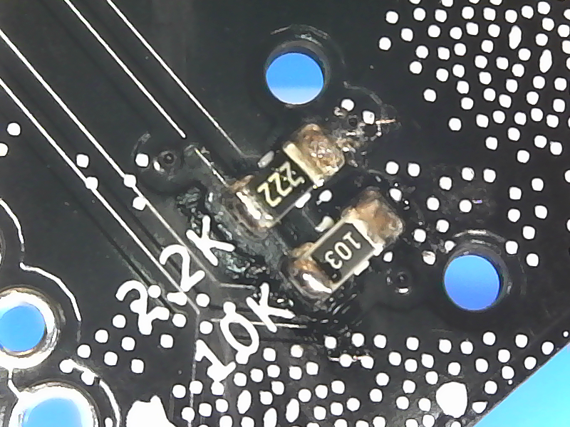
Alright, first thing you’re going to do is grab 5 10K resistors (103), solder those onto top and bottom, they’re labeled on the board but you may need a magnifying glass. Repeat this with the 220ohm resistor (221).
If you are installing the LED hardware bridge the two pads together on the side with more resistors (The pads with a round marking), this enables power to flow to the LEDs, if you want to turn them off desolder this jumper.
Now on the topside solder in the button, tack an edge, align it, solder it! For the LEDs there is a little arrow on the rear of the diode, The thick side of this arrow is the anode, match the thin side of the arrow with the marking on the board. Thin, in the box!
Now go over every one of your connections with a magnifying glass. make sure they are forming a nice connection with their pads.
Cool, every part should be on the board now. After you’ve checked your connections (did I mention to check your connections?) you should tin one pin of the staggered pads on the bottom. This is going to be where the pins will be mounted. Take your pins and cut off the amount you’ll need matching the orientation! Don’t worry about how flat they are right now. Take the board and placing it on a level surface heat the corner of the pad (not touching the soldered pin). Once the solder reflows and the pin drops flush with the board check the alignment and solder the other legs down. Repeat this process for the other two sets of pins.
You should now have a fairly complete trackball. Let’s test it! Solder the headers (DON’T CLIP THE LEADS) onto the funky key on your Gergo and slot the module in. DON’T FORCE IT. If the pins are aligned wrong try moving them on the board or reheat the header connections on Gergo and massage them towards the correct alignment. If you’ve done this correctly, plugging in your TB will turn on the LEDs, if not check your connections
After you have Gergo configured and QMK running enable BALLER_DEBUG and CONSOLE_ENABLE in keyboards/gergo/rules.mk, flash your firmware and run hid_listen as root. If you’ve done everything correctly there will be next to no output until you put the ball overtop of the board. If instead your cursor is drifting, check your connections.
Now that your ball is half working you’ll notice a ton of jitter from it sloshing around. Apply a small bit of epoxy to the holes on either side of the button and press the ball into place. If you’ve opted to use LEDs, trim the legs down with flush cutters as much as you can before doing this.
Lastly drill a hole in your least favourite keycap and mount it on there with tape or funtac. You’re going to need to get creative on that one. If you wish to level it with you keys, heat and raise the headers. Once it’s leveled and working you can now clip the leads.
Configuring Gergo:
Protip: Use rubbing alchol to clean up any remaing flux on your board! If you know what you’re doing just run this
- git clone https://github.com/qmk/qmk_firmware.git
- cd qmk_firmware
- make gergo:default:dfu
There are a few ways to get your firmware onto your keyboard. You can either use command line tools (recommended) or modify it online using config.qmk.fm
Otherwise you’ll want to take a watch through this tutorial.To modify your keymap simply modify layouts/community/ergodox/germ/layout.c with the desired keycodes from the QMK Keycode List
If you have any improvements feel free to submit a pull request!